
This article contains paid affiliate links. These links help you get directly to the products listed and they also help us earn a small commission at no cost to you.
So much can be done at home with HVAC, home AC, and home Heating units. I love sharing guides to help with all of your home projects.
Are you looking for more DIY Home Improvement Ideas to save you money? Check out some of my most popular posts-
How to Install an Electrical Sub Panel for “DIY” ers.
Home Renovation Ideas as you head into Spring
Organize Your Kitchen Cabinets with DIY Shelving
If you’re considering installing a Mini Split Heater / Air Conditioner, there’s a lot to it that doesn’t get explained well in other videos or articles. My goal is to remedy that and walk you through every bit of it. For those who prefer a video format for this sort of thing, check out my video: DIY Mini Split Install – All the Things Nobody Shows You.
I have created some diagrams and charts to help explain the layout, the steps and the electrical requirements for this project. Before we dive in, I want to encourage you to try this yourself. This is one of those projects that can be daunting but if you’re patient and work your way through it, the benefits are incredible. You may need some new tools for this but most are pretty affordable, especially in comparison to hiring the work out. That said, if any of this is beyond your comfort level there are pros out there that can help and they’ll likely do a great job and save you some time. I’m way too cheap for that though, so let’s dive in!
PREP STEP 1: CHOOSING A MINI SPLIT
Determining which mini split to buy is your first order of business. I’ve seen a lot of ads and videos featuring the Mr. Cool DIY Gen3 Mini Splits so I started looking into those. As it turns out, there are three main differences between those and most others.
- Quick Connect Linesets – the lines between the indoor and outdoor units use a quick connect fitting, which is quite convenient.
- Pre-charged R410A Linesets – the same lines mentioned above don’t need to be evacuated using a vacuum pump. This again, is a nice feature that will save you time and energy.
- Built-in WiFi – I’m a big smart home guy so this is really appealing.
BUUUUUTTTTT….
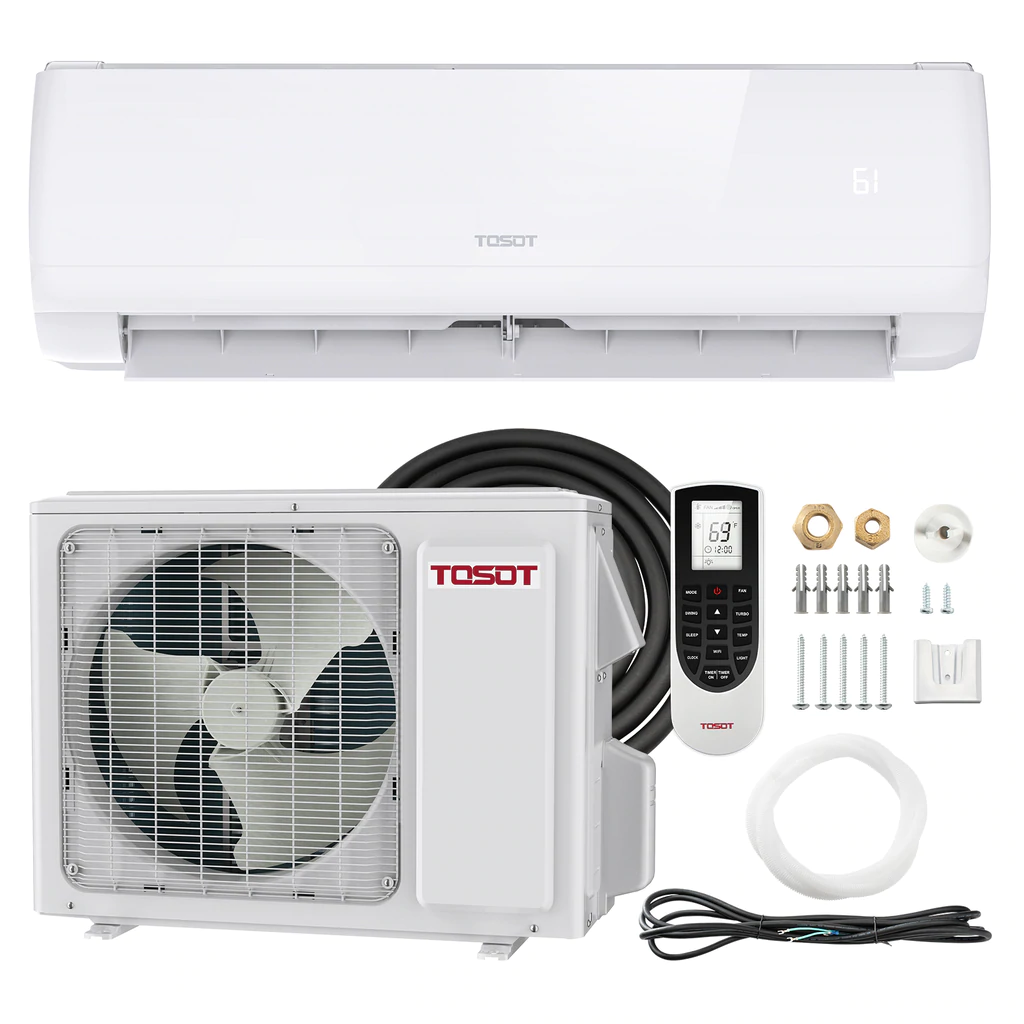
There’s a catch. The cost. If you look up a TOSOT unit (the kind I installed) and a Mr Cool of comparable specs, the TOSOT costs $919 USD while the Mr Cool costs $1497 USD. That’s a $578 difference. Is it worth it? It may be to you, but not the way I see it. Let’s look at those three items again:
- Quick Connects – This is nice but it only saves you a few minutes (literally) of time. If you have two adjustable wrenches you can connect your lines really quickly and easily.
- Pre-charged linesets – This is the biggest advantage of the three, in my opinion. Later in this guide, we’ll walk you through evacuating the lines yourself. It takes less than 30 minutes and costs $129 USD. I promise it’s pretty straight forward and my video shows you exactly how to do it – plus we’ll explain it all here too.
- Built-in WiFi – This one was a bummer for me to see that my TOSOT unit doesn’t have this… until I realized I can add it for $85. I ordered a Sensibo Sky – a WiFi unit that allows me to take full control of my mini split (or any mini split, AC Unit, window unit – whatever) and even use my voice with Alexa, Google or Siri to control it all.
So in total, we’re looking at spending $214 plus an additional hour or so in order to save $578. I don’t know about you but I’ll gladly spend an hour to save $364. Now, if I could just figure out how to earn $364/hour all the time…
What Size Unit Do You Need?
Most mini split units offer a rating for the maximum square footage they can condition. The TOSOT 9.000 BTU unit, for example, says it can handle up to 450 Square Feet (around 42 square meters). The 12.000 BTU unit can handle up to 650 Square Feet (around 60 square meters) and the 18,000 BTU unit can handle up to 850 Square Feet (79 square meters). Consider other factors besides just the square footage of the area you’re trying to heat and cool, however. Here are a few factors that can have a significant impact on what size unit you might need:
- Insulation in the walls and ceiling
- How many windows or doors
- Ambient temperature (are you in San Diego where it’s close to room temperature all the time?)
- Devices or appliances that produce heat in the space
- Usage – if it’s in use all the time, you’ll likely run the mini split all the time, but if it’s not maybe you can get away with less?
STEP 1: PREP & INSTALL YOUR INDOOR UNIT
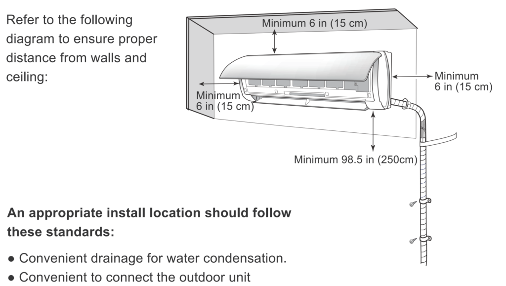
Once you’ve decided on which unit to get, the first thing to do is to prepare and install the indoor unit. Here are some guidelines for determining where the unit can be placed.
- It has to be mounted on a wall that has access to an outside space. Ideally this will be an external wall but it can also be a wall that allows you to run a line to the roof, for example.
- It needs to have at least 6″ of clearance above and to either side of it.
- It needs to have as much room as possible below it – ideally 8-9 feet but since that’s not possible in most spaces, you can put it as high on the wall as you can while still leaving the required 6″ above it.
- It should have plenty of open space in front of it for the air to circulate. Be sure not to tuck it behind furniture or in a nook of the room that won’t allow for proper air circulation.
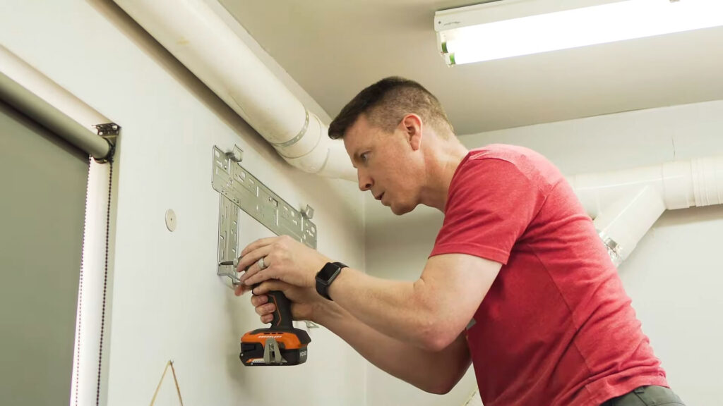
Once your location is picked out, you can use the mounting bracket as a template to mark the holes for the unit. Be sure to use a level for this so that your unit is nice and straight. Use a 1/4″ drill bit in a drill to predrill the holes for the wall anchors, if necessary. If you’re working with a concrete or brick wall, be sure to use the proper masonry bits for this. Insert the included wall anchors and secure the mounting bracket to the wall. Typically about 5 screws is sufficient seeing as how the unit weighs around 23 lbs.
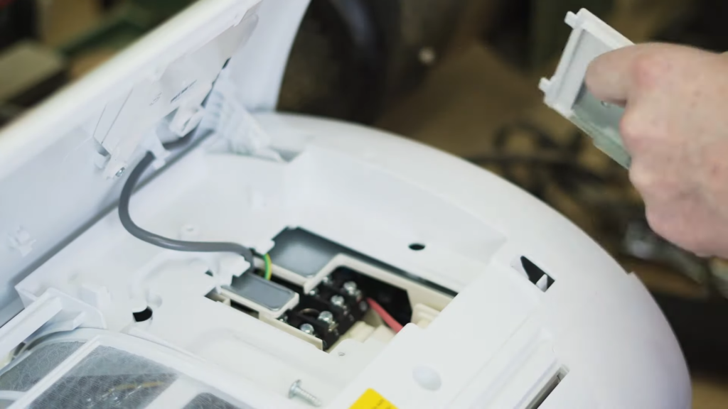
Next we need to prepare the indoor unit itself. Start by lying the unit on a clean surface, face up. Lift the lid and you’ll find a service panel that is held on by one screw. Remove the screw and set the panel door aside. Under that panel you’ll see a set of terminals and a cable harness, which is typically secured by one screw. Remove that screws as well.
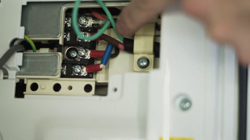
You’ll then need to grab your signal wire. There are typically two sets of wires that come with the unit – the first is a power set that has three cables – line, neutral and ground. The signal cable, on the other hand, has four wires in it. Be sure to consult your manual on this to ensure you have the proper cables. This will need to be fed into the rear of the unit. There is often a feed loop you can pass it through and then you’ll need to secure it with the wire harness. Pull the wire through to the front and connect each U-bracket to the appropriate terminal. Don’t get too hung up on which one goes where since all that really matters is that you use the same wires on the same terminals on the outdoor unit.
With the wires secured to the terminals, fasten the wire harness over the sheathed portion of the wire and close the panel back up. Now flip the unit onto its front to expose the back of it.
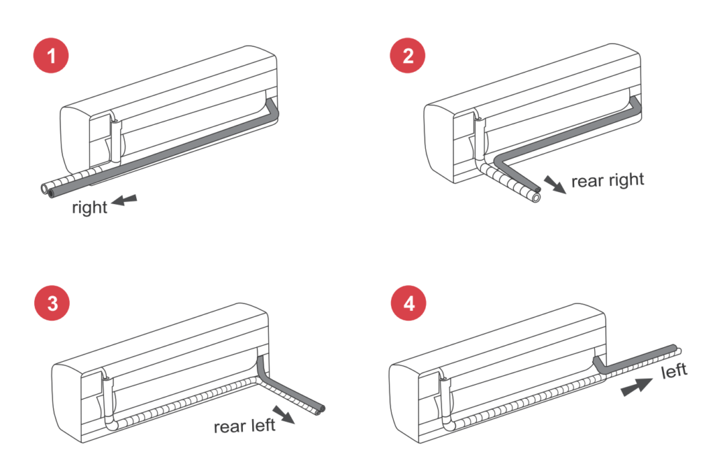
The next step is to determine which direction your lineset (the two insulated copper lines plus the signal wire and drain pipe) will exit the unit. It can either be out the left side, left back, right side or right back. You can see in these images that mine is heading out the left back. If you’re taking out one of the sides, you’ll need to trim the decorative covers to make room for it. You can do this by using some wire cutters or even some scissors to cut the appropriate panel out. The copper pipes can be bent gently to the direction you need to go – just be sure not to bend the lines too sharply. A kink in these lines would severely limit their ability.
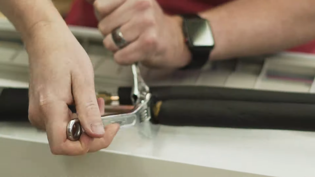
Press in on the pressure release valve located at the end of the high pressure line (the smaller of the two with the black cap) using any sharp-ish object. I just used the corner of my adjustable wrench. You’ll hear a big pressure release, which is what you want. Twist off the caps from both lines using pliers or a wrench. This is a good time to put the linesets in their correct position if you haven’t already. If your linesets are going to exit the unit on the opposite side as the drain line, you may need to add the drain extension in order for it to reach the lineset before the next step. At this point you should have your signal cable, two insulated copper lines and your plastic drain pipe ready.
Next we’ll need to add the full length linesets to the existing shorter ones. Take your coiled linesets and put one end of each on the floor and then, while gently stepping on them to hold them down, unroll them until they’re somewhat straight on the floor or the ground. I didn’t have enough room in my shop to do this so I had to take it outside.

Remove the caps from one end of each line and use adjustable wrenches to fasten each line to the existing lines on the indoor unit. It’s up to you but there’s a product called Nylog Blue that is intended to help seal these types of connections. You can put this on the ends of the connections to keep things sealed if you wish. I didn’t use this and had no issues but it may help to keep things tight. I won’t mention this for the other connections but you can, of course, apply this to all connections for your copper pipes.
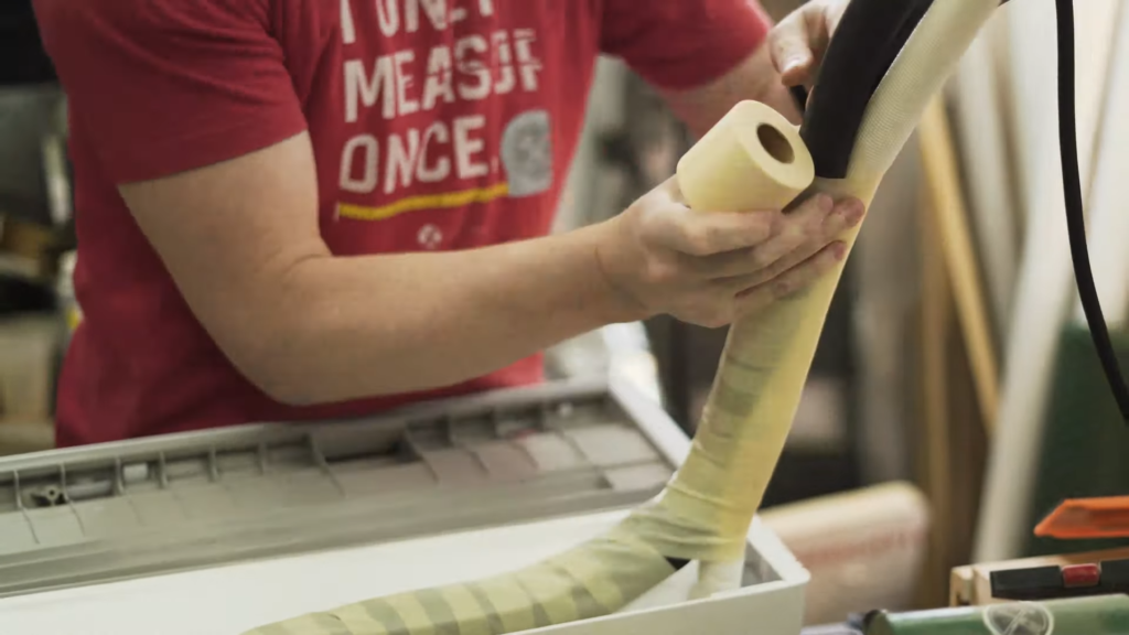
Now that you have the full linesets, the long signal cable and the full drain pipe connected, you’re ready to start wrapping everything with the included nylon tape. Start at the base of the lineset and wrap the two insulated pipes together along with the signal (and drain if you’re on the opposite side of the drain source). You’ll want to get to the point where, by the time the lineset pulls away from the unit, you’re wrapping all four lines together at once. continue this until you’re about 18″ away from the end of the insulated copper lines. You can then wrap the two copper lines individually, leaving the signal wire separate. I did this later on in the process but it doesn’t matter much which you do first. Just keep in mind that you’ll ned to fit this all through a small hole in the wall next.
Speaking of which, that’s the next step – drilling a small hole through the wall to the exterior of your home/building. You should be able to use a 2 1/8″ hole saw to get through the drywall or interior of your room but if you have brick or block, you may need to use a masonry hole saw. You can use a hole saw anywhere from about 2″ to 2 1/2″ but I found that a standard 2 1/8″ saw worked great. There will likely be insulation in the wall that you’ll need to work around.
It’s important that you drill this hole at a slight 5-10° downward angle, with the lower end being on the exterior side. The reason is so that if any moisture or condensate gets in this area it will slope downward and out.
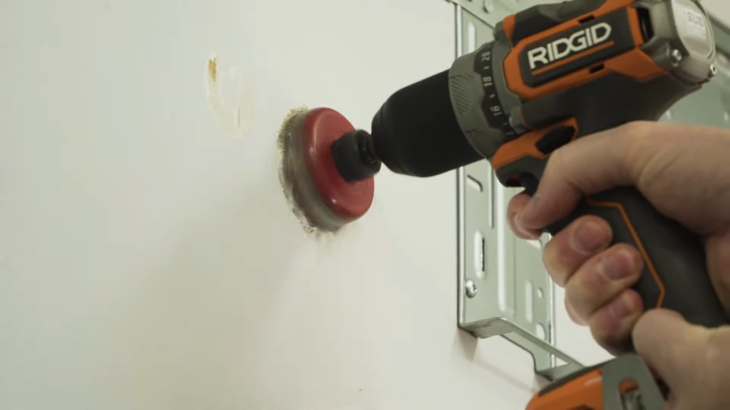
Because the hole saw may not reach the outside wall or may not be capable of getting through to the exterior, you may want to use a longer 1/4″ drill bit from the inside to get to the outside. Remember to keep that same 5-10° angle as you do so. Now you can move to the outside of the building to drill the other side. Line your hole saw’s pilot drill bit up with the hole you drilled from the inside and drill at the slight upward angle to finish off the hole. Again, depending on the material on the exterior of your structure you may need to get through stucko, stone, concrete, wire mesh or any number of things so your drill bit will need to accommodate that.
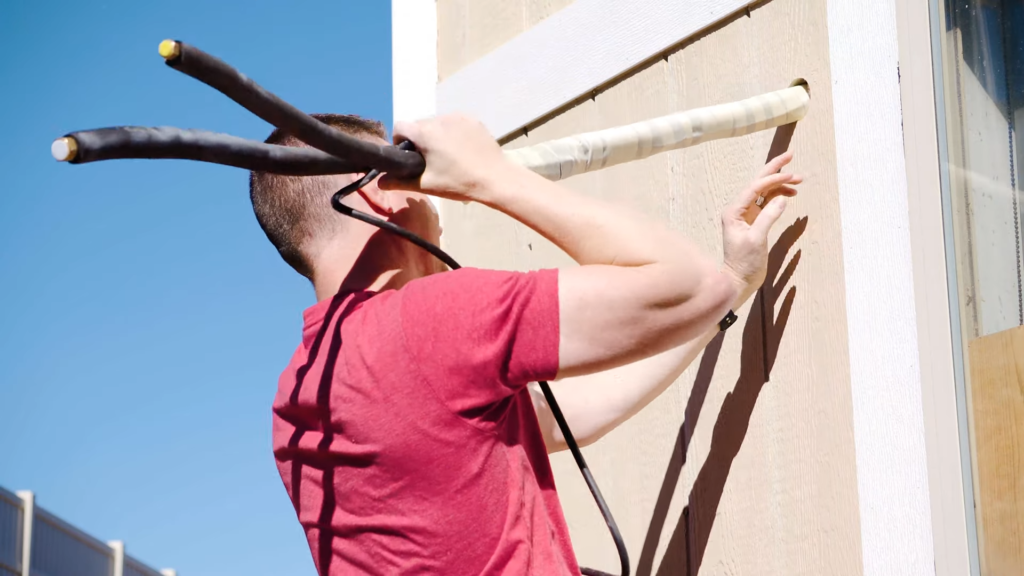
Now for the fun part – you get to feed the wrapped lines through the hole so that you can mount the indoor unit to the wall. While this can be done by yourself, I highly recommend getting a helper. I did this while my wife was out and it would have been a lot faster and easier to have her help me. The line needs to be pushed in until the unit can be hooked onto the top of the wall bracket and then the bottom can be snapped into place, making the whole unit flush with the wall. The inside is done!
STEP 2: PREP & INSTALL YOUR CONDENSER
With your lineset hanging out the exterior, we have one bit of cleanup to do before moving forward. Your mini split comes with either a sleeve or a collar (or both) that go around the lineset and get pushed into the hole where you fed the lineset through. In my case, it’s a collar. The kit also comes with some sealer – mine was called “GumType Sealer”. Haha! You need to push this into the hole around the lineset to seal it up so there’s no way anything’s getting in there, then slide the collar into the hole to seal it off. I recommend you caulk all of this but we’ll get to that later.
You’re now ready to put your condenser in place! You have several options here and a lot of this depends on the placement of the indoor unit. Be sure to check the length of your lineset to see if there’s enough length to get from the indoor to the outdoor unit. Most kits come with 16-25 feet. If you’re installing this on the first floor and it can easily reach the ground outside, that’s probably the simplest situation. You may, however, have the indoor unit on the 3rd floor, in which case you can either place the condenser on the roof, mount it to the exterior wall near the 3rd floor or even place it on the ground and run your lineset with an extension down to the ground. Extension linesets are available from pretty much all manufacturers.
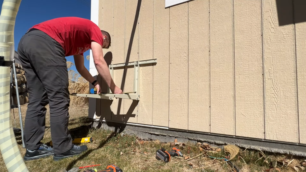
When it comes to mounting options, you can pour a small concrete pad and bolt it to the concrete but what I found to be more convenient, faster and less expensive is to use a mini split condenser wall mount. These run from $30-$80 and can be shipped to your door pretty conveniently. When using this option, be sure to locate the studs on your wall so that you can mount the arms or the rail that the arms attach to directly to the studs whenever possible. You can use a stud finder for this but the easiest way is often to use a stud finder on the inside of the house/building and measure the distance from a common marker, like the glass in your window, to the nearest stud. You can typically then measure 16″ in any direction to find the next stud. Follow the instructions included with your mounting kit to get it in place.
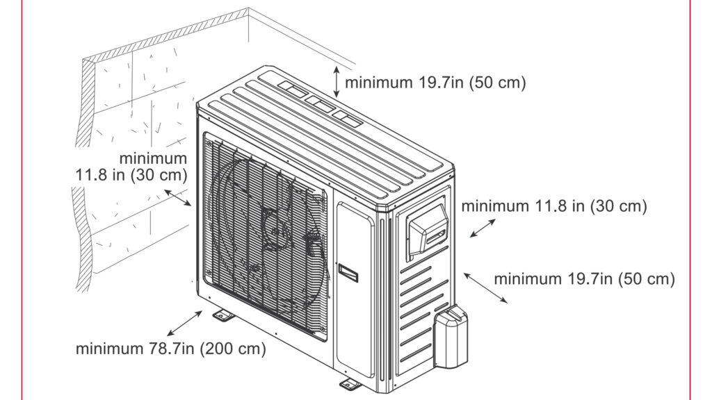
Whichever method you go with, be sure to leave sufficient room around the condenser. There needs to be about a foot to the left and rear of the unit, 20 inches to the right and top of it and 6.5′ (2 meters) of open space in front of it.
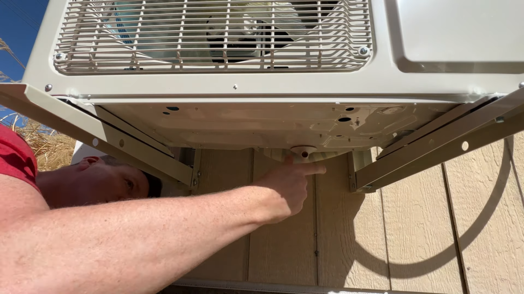
As you’re installing your wall mount, be sure to measure the distance between the mounting holes on your condenser unit to see where the arms of the mount need to go in order to accommodate the mounting hardware of the condenser. Once the mount is installed, put your condenser on it and secure it using the included nuts and bolts. Be mindful of the fact that there is a front and back of the condenser. The connections for electrical and linesets are typically on the right side as you face the house. There is a drain connection that needs to be attached to the bottom of the condenser once your condenser is in place.
We’re now ready to connect our linesets! Make sure the drain pipe is in a place where it can drain freely and cut it to length if need be. Any excess lineset can safely be coiled in circles behind the condenser. Alternatively, if you’d like to cut the lines to the exact length needed, this is ok to do on any non pre-charged lines. All you need is a simple, inexpensive pipe cutter to cut the copper to length and then a flaring kit ($25 at Harbor Freight). Slide the nuts up past the length you’ll be cutting, cut the pipes to length, flare them using the kit, then slide the nuts back into place around the new flares.
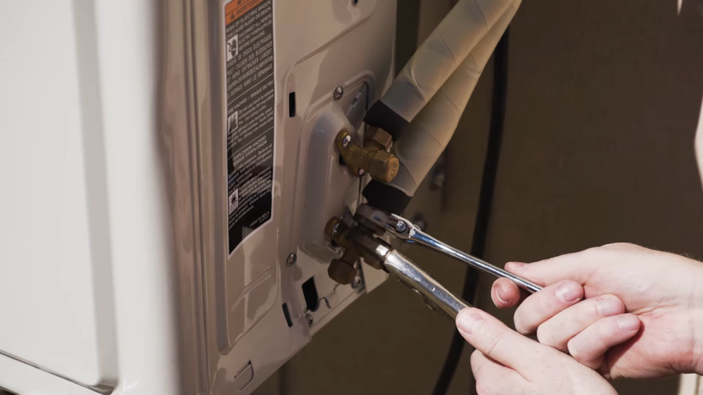
Assuming you’re just going to coil the linesets, you can get them into position, remove the two caps for the high and low pressure lines, remove the plugs on the linesets and then fasten the lineset lines to the condenser inputs. Again, Nylog Blue is a good option here if you choose to do that. Tighten everything using two adjustable wrenches. If you’re using pre-charged lines, this may be the end of your connection process. You can skip ahead to opening the valves.
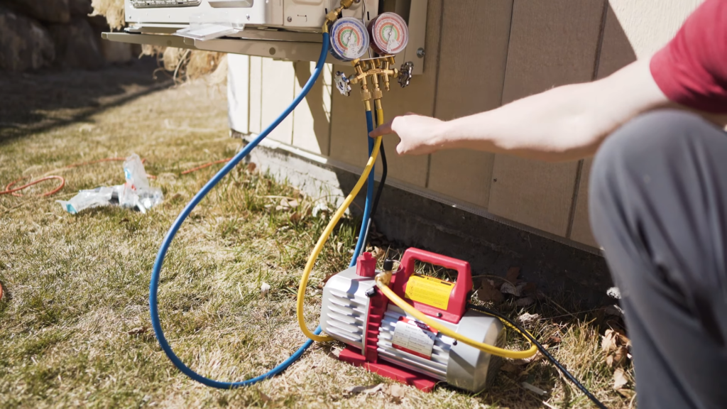
Assuming you need to evacuate your lines, once linesets are tight you can remove the other three caps – the two valve covers and the service port. This is the part where you’ll need some extra tools to evacuate the lines. I suggest a kit like this that comes with everything you need in one purchase. The tools you’ll need are a 3-5 CFM Vacuum Pump (3 CFM is typically sufficient for a 12,000 BTU unit but you may want to get a beefier pump for an 18,000 or 24,000 BTU unit), a manifold gauge set and a 5/16” Quick Coupler to 1/4″ Male Adapter. All three of these are included in the kit I mentioned above.
Connect your manifold hoses as shown below, with the yellow line going from the pump to the center manifold port and the blue line going from the left manifold port to the service port on the condenser. The red line doesn’t need to be used but be sure to close the right valve on the manifold gauge. Once everything is set up, here are the steps to evacuate the lines:
- Open the left valve on the manifold.
- Turn on the vacuum pump.
- Set a timer for 15 minutes – notice the gauge reading on the left-most gauge. It should read in the negatives.
- At or after the 15 minute mark, turn off the pump and close the valve. Verify that the gauge reading is still in the same place. If so, proceed to the next step. If not, repeat steps 1-4.
- Set a timer for 5-10 minutes and monitor the gauge. It should stay put. If the needle moves, that means you’ve got a leak in your lines somewhere. If it stays still, proceed.
- Spray some soapy water onto the connections of the condenser and watch for any bubbles that start forming. This indicates a leak in the connection and it needs to be tightened.
- Once there are no more bubbles, you’re all set! You can disconnect the vacuum pump from the service port.
- Lastly, open the valves on the high and low pressure ports using a 5mm allen key. Turn until you feel the valves are all the way open and won’t go anymore. Replace the caps on the service port and valves. Put the port cover back on the condenser using the two screws that hold it in place.
Congratulations! You now have the linesets all done and all that’s left is the electrical work!
STEP 3: RUNNING ELECTRICITY TO YOUR CONDENSER
With our linesets in place, it’s time to run electricity to your condenser, which will also power your indoor unit. This is slightly involved electrical work and I highly recommend you either consult with an electrician, have them review your work or that you hire the electrician to do it. Please take all necessary precautions when doing any electrical work. I’m going to walk you through all of the necessary info for determining what size wiring, voltage and breaker you need but it’s best to get this info verified with the manufacturer and a certified electrician.
Your mini split should indicate whether it is a 110v volt or 220 volt. On that note, 110 and 120v are the same – it’s just a voltage range. Same with 220v and 230v. The BTU rating will determine the breaker size needed and, therefore the gauge of wire required to power the unit. You can use the chart below to determine the details for your install.
In the United States of America, any AC Condenser installation requires what is called an AC Disconnect to be installed within a few feet of it. This is so that a service technician can turn power off to the unit easily while servicing it. This may or may not be the case in other areas outside the U.S. – please check your local code. l
Here’s a diagram of what the entire sequence looks like, from the Indoor unit all the way back to the circuit breaker panel.
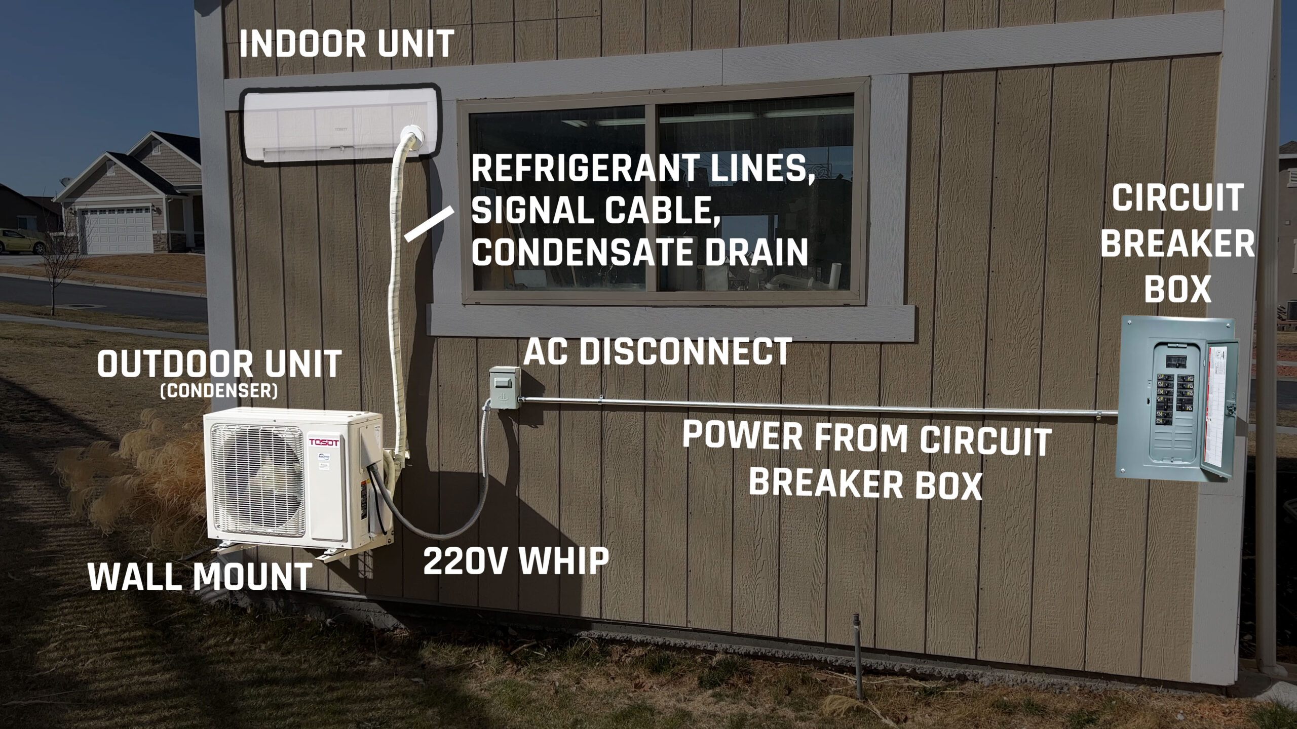
The location of your circuit breaker box in relation to your condenser will determine your work flow here but the important thing is that you’ll need a new, appropriate sized circuit breaker in your panel, which is connected to appropriate sized Romex cable, which connects to your AC Disconnect. You’ll then run what is called a whip from the AC Disconnect to the condenser. A whip is basically just an outdoor rated set of electrical wiring for connecting AC units or other large appliances to a disconnect box – exactly what we need for this situation.
Determining Circuit Breaker and Wire Size
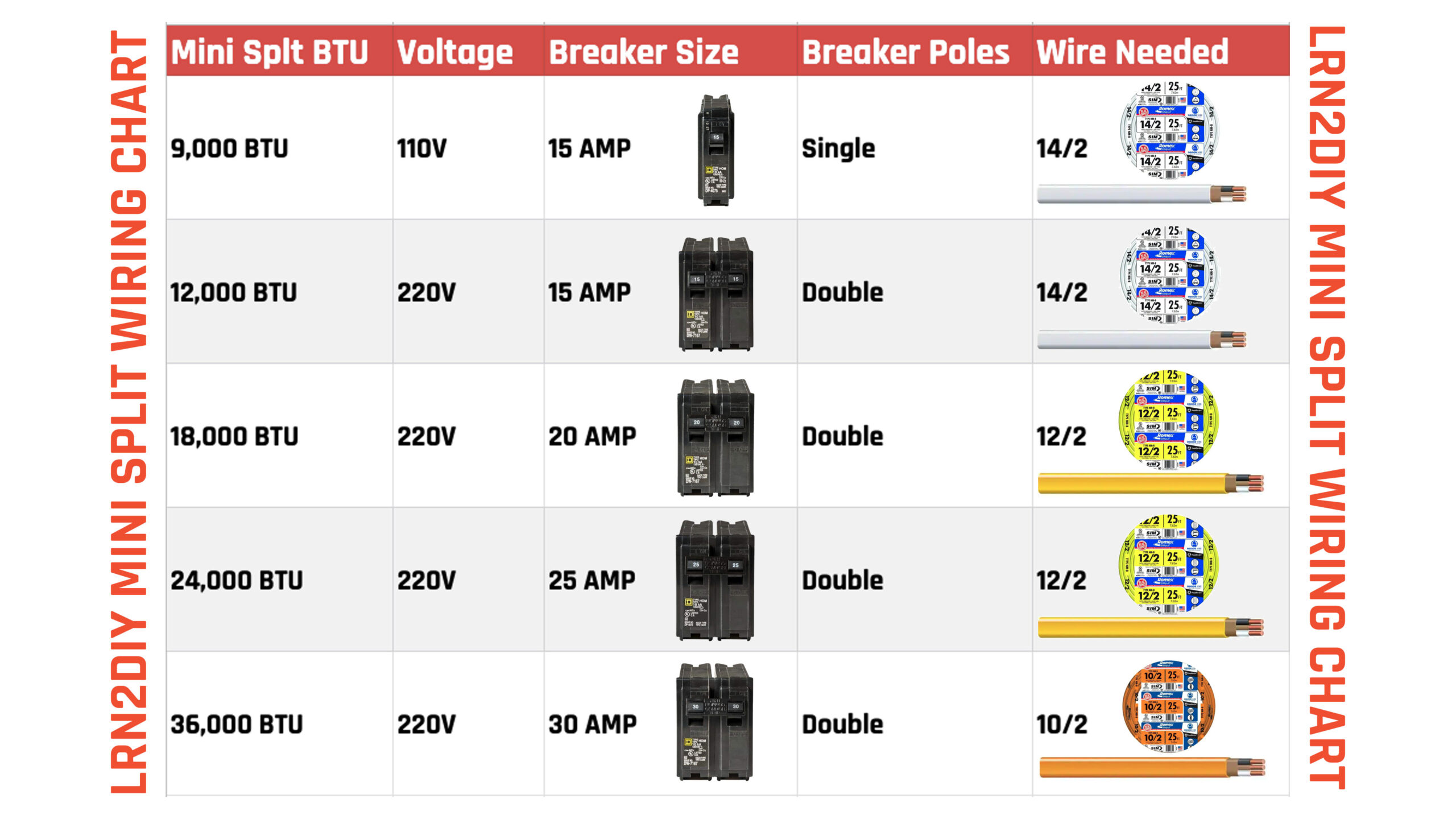
Using the chart above, you should be able to determine how many amps your circuit breaker needs to be, whether it needs to be a single or double pole breaker, and what gauge wire to use to connect it to the AC Disconnect. Because I was running a 12,000 BTU 220v mini split, that means I would only need a 15 Amp Double Pole Circuit Breaker and some 14/2 Romex. If you have a 12,000 BTU 110v, you can use the 15 Amp Single Pole Circuit Breaker instead, but still with some 14/2.
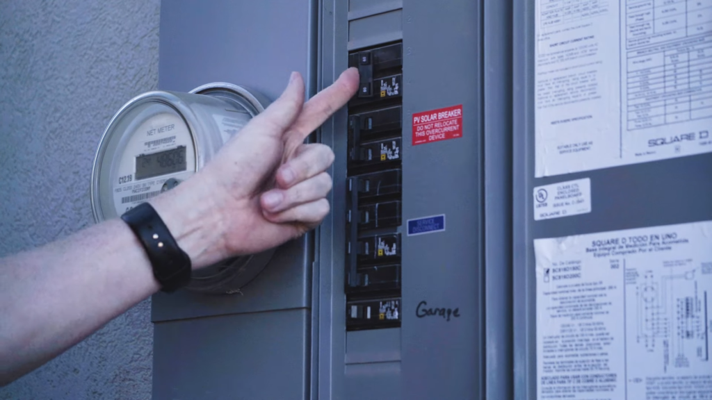
IMPORTANT SAFETY NOTE: Before you work on anything in a circuit breaker box, you HAVE to turn off the power to that box entirely – it could be the main for your house or, if there’s a subpanel, it could be a circuit breaker that controls the power to that subpanel. If you’re at all unsure about this, please consult an electrician!
Just to clear up any confusion for the images you’ll see next, I had a 15 foot roll of 10/3 Romex sitting around in my shop that I didn’t end up using in a previous project so I decided to just use that, which is why you’ll see orange Romex in my setup. Also, when you’re running wire, it’s always a good idea to match the wire gauge to the circuit breaker. For this reason, I installed a 30 Amp Double Pole Circuit Breaker in my panel because that means I have the option to install larger appliances, additional outlets or other items in the future if I so desire. Sometimes if people see a 10/3 wire, they may assume there’s an equally powerful circuit breaker on the other end so they can add a larger appliance – I wanted to give future users the benefit of the doubt, especially since the cost difference is negligible.
This next portion can vary quite a bit depending on your home or building. In my case, I have a subpanel for my woodshop located near the back wall of the shop, not far from the condenser. I decided to drill a hole into the corner of the shop directly to the panel, and then connect the wiring using outdoor rated EMT to the AC Disconnect.
My first step was to remove the circuit breaker panel cover and open the drywall where I needed to run wire. This can certainly be intimidating but patching up drywall is easier than you might think. I have a video that shows five ways to patch drywall that you might find helpful.
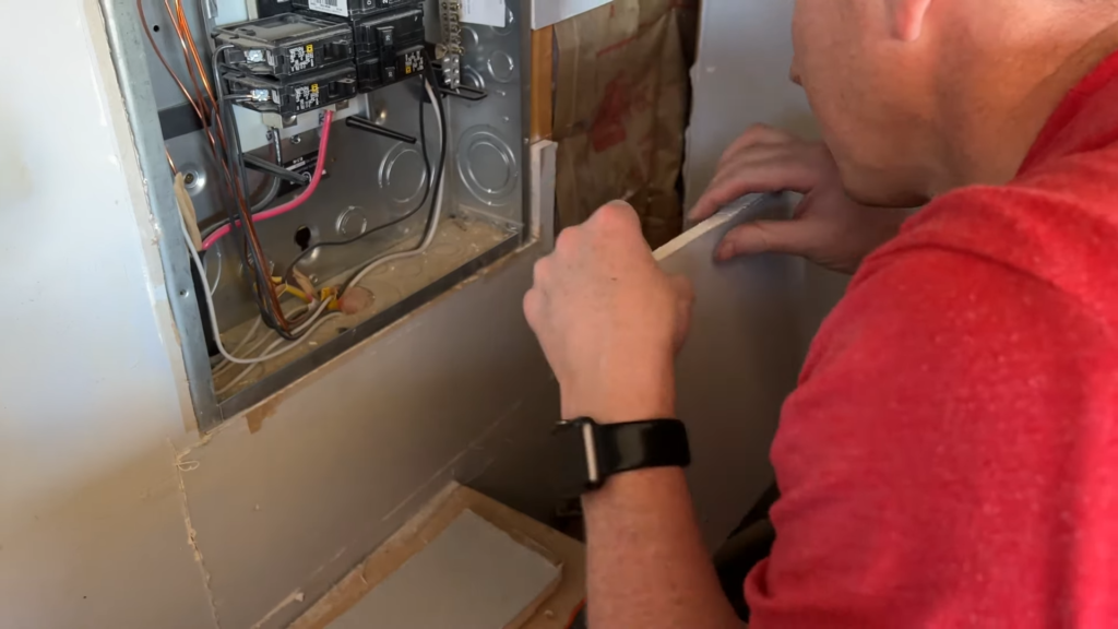
With the drywall open, we can drill a hole from the outside of the building using a 1 3/8″ forstner bit and then use a 1″ drill to get through any studs between the circuit breaker panel and the newly drilled exterior hole. Be sure to drill the stud holes in the middle of the stud to help prevent any accidental piercing of the wire later on. You’ll also need to use one of the knockouts on the panel to feed the new wire in. If you haven’t knocked out a knockout before, you can just use a screwdriver, hammer, pliers – whatever it takes. There are several expansion rings to fit different size fittings.
Next we’re going to run some wiring through, but before I continue –
DID YOU KNOW THAT ROMEX IS ACTUALLY CHEAPER ON AMAZON THAN IT IS AT THE BIG BOX STORES!!?
I had no idea! Especially since Home Depot usually sells things cheaper than Amazon because of their quantity buying. Links to all the varieties of Romex on Amazon are in the supplies list below.
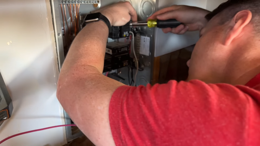
Feed your wire in from the outside location, through the studs and right to the box, but not into the box yet. Before you feed the wire in, you need to put a collar on it. This screws tightly onto the wire to hold it in place and then snaps into the box of the panel through the knockout hole. Place the collar far enough down the cable to allwow you to reach all the necessary bus bars and circuit breakers in the panel. Once that’s in place, snap it into the box, then remove the sheathing on the cable. My favorite way to do this is to use a blade to cut along the end of the cable to open it up (cut along the length to avoid snipping wires) and then grab the sheathing and open it by pulling back toward the collar. Carefully cut off any excess sheathing and remove the paper liner from the sheathing and the ground cable.
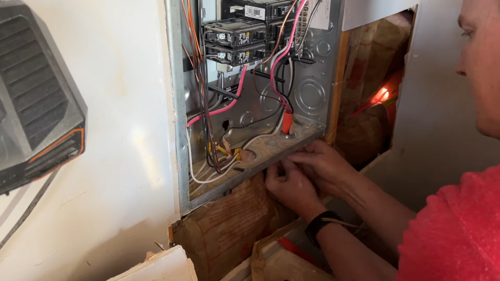
The circuit breaker snaps in by hooking the outside edge into the housing and then the inside portion can be pushed onto the metal stud until it snaps into place. It’s actually really simple. In my case, I had an extra wire (the red wire) that wasn’t going to be used so I capped it and laid it at the bottom. I ran my ground wire to the ground bus bar and my black and white (load and neutral) wires to the new 30 Amp Double Pole Circuit Breaker – one wire per pole. That’s it! If you’re using a traditional 10/2, 12/2, or 14/2 wire and a double pole breaker, it’s the same process minus the extra red wire. For single pole breakers, connect your black wire to the circuit breaker and your white to the neutral bus bar. To finish off this portion of the job, put your panel cover back on and then it’s up to you if you want to do the drywall work now or later. I just put my drywall back in place temporarily for now.
With that wired up, we can work on the exterior connections. I fed my Romex through what I call an elbow (an EMT Set Screw Conduit Body) and pushed one side of it into the hole I had drilled. I then cut some 3/4″ EMT using a basic pipe cutter, and I reamed it out using the included reamer on the back end of it. I used a pair of 3/4” EMT Insulated Compression Connectors, one on each end of the EMT. One threads into the elbow and the other will go into the AC disconnect. Feed your Romex cable through the EMT once the connectors are in place and use some pipe straps to mount the EMT to the wall, making sure to level it before doing so.
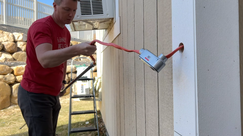
At this point you should have your power cable coming from the circuit breaker, through the wall, to the EMT on the outside of the structure, coming out of the EMT and then to the location where you’ll mount the AC Disconnect. If you need additional runs of EMT, be sure to add them and you can also find elbows, connectors and whatever else you need to make a longer run if necessary.
OK – we’re getting really close here. Time to hook up our AC disconnect. These only cost about $13 at Home Depot or you can find them online as well. The basic idea is that they have a bar on them that can either connect all of the power lines or intentionally keep them disconnected for servicing. Determine where this needs to go, punch the appropriate knockout out on the disconnect, and slide your EMT connector (from your long EMT pipe) into the knockout. There are several holes on the back of the disconnect that can be used to mount the box onto the wall. I recommend using outdoor rated screws for this to prevent rusting later on. Here’s a look at how the wires can be connected inside the AC Disconnect but the idea is that both grounds go to the ground bus bar on the bottom and then your line and neutral incoming wires go on the center two terminals, while the outgoing (whip) line and neutral wires go on the outside terminals. Make sure you have the two lines next to each other (shown on the right side) and the two neutral together (left side).
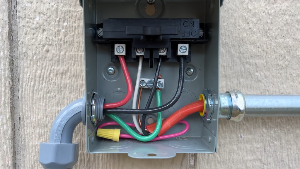
Don’t mind my extra red wire there again 🙂 It won’t be used right now but it’s there if I need it later.
As you may have guessed we need to install the 1/2″ whip next. The first part of this is to remove the wires from the whip (typically red, black and green) then cut the whip sheathing to length. These usually come in 6′ lengths but just make it long enough to get to the condenser with an additional foot or so for slack. No need to make it too taut. You can use a utility knife to cut the sheathing – it cuts pretty easily. Once that’s cut you can thread the end nuts onto the sheathing. They have threads inside their receiving slot that grab onto the sheathing. Punch your knockout for the other side of the AC Disconnect and feed one end of the whip into it then fasten the nut on it. Feed the wires back in and cut them to length, leaving 6-8″ on either end, then strip the last 1/2″ of each wire on both ends. Wire the AC disconnect as shown above.
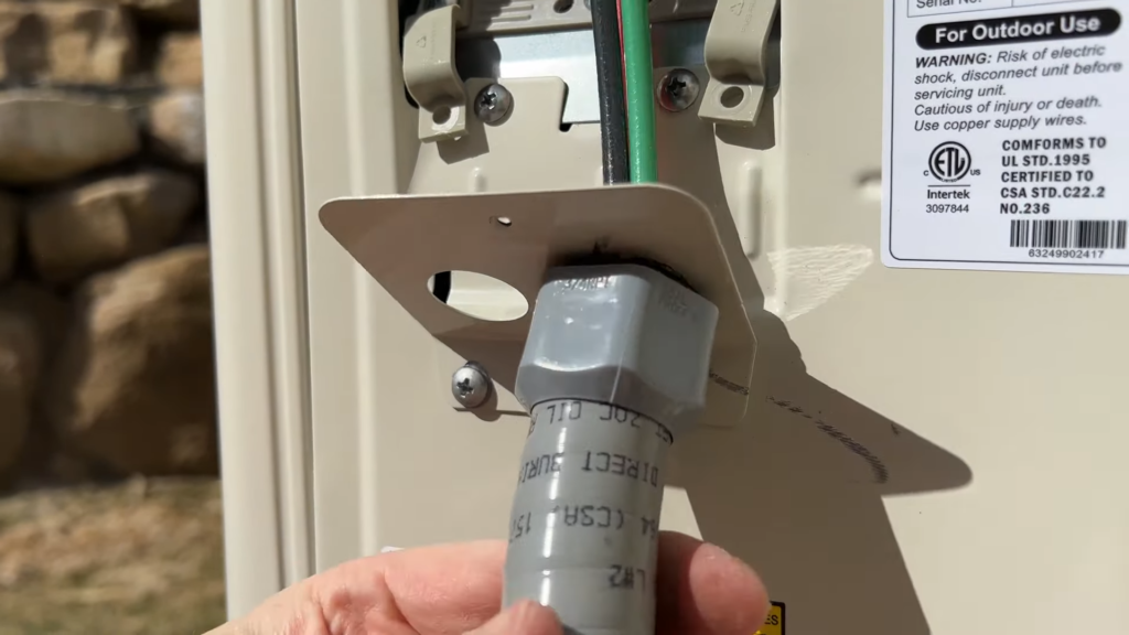
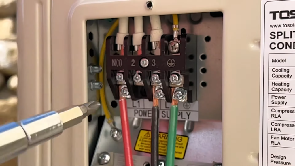
On the other end, push the threads through the receiving hole on the condenser and then thread the nut onto the threads to hold it in place. Wire up your condenser as shown, with the red wire in the first terminal, black (line) terminal in the 3rd terminal and, of course, the green/ground in the ground terminal. Be sure to consult your manual in case your mini split’s wiring should be different.
All that’s left is to connect the signal cable! W00t W00t! Feed the signal cable through the lower hole, just like you did with the whip and then connect it in the exact same order you did on the indoor unit. Here’s how mine look for reference.
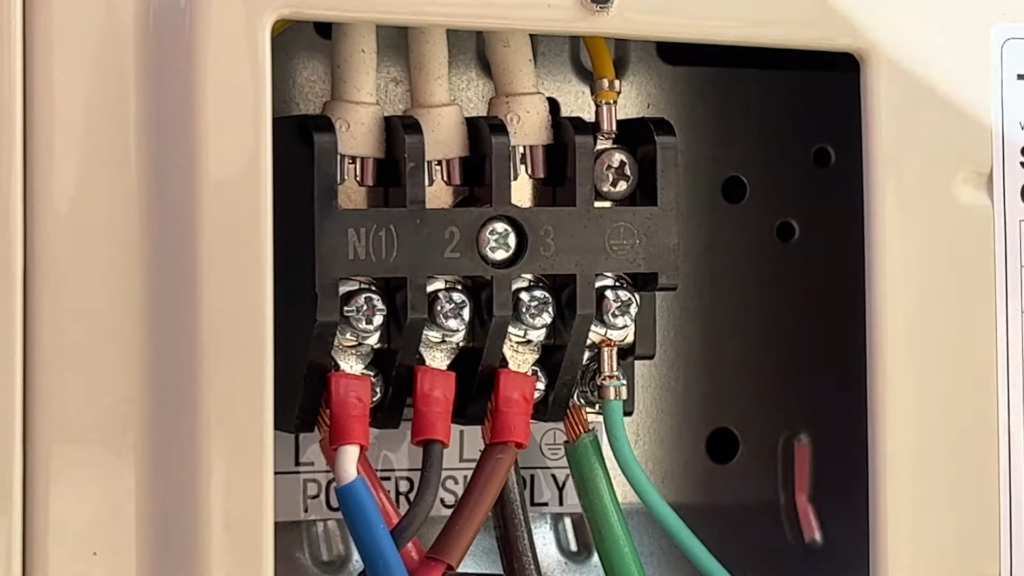
Again, be sure to check your manual to verify how this should be set up, but if you’re wiring these in the same order that they were on the indoor unit, that’s all that really matters.
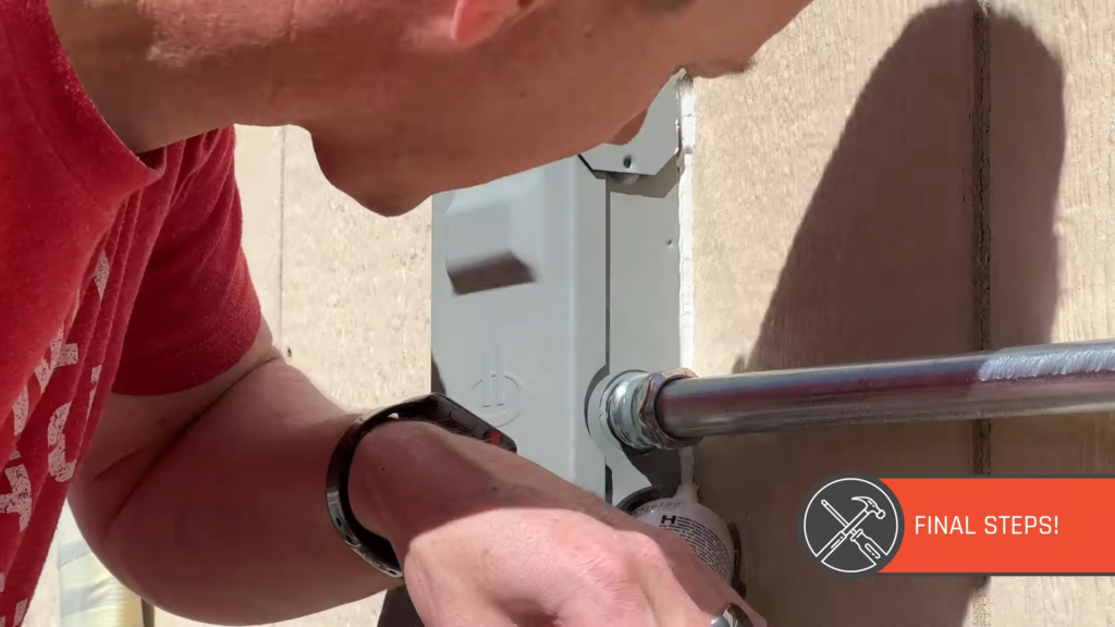
Once that’s wired up, replace the cover with the two included screws and all that’s left is to do some caulking to weather seal everything.
I recommend caulking the EMT elbow where it goes into the wall, the AC disconnect and the lineset sleeve – basically everything that might allow entry of water, critters or the elements into the structure.
OK, the indoor unit is in place, it’s connected to the condenser, there’s power going to it and everything is ready to go! Now you need to flip the power back on at the main panel and/or subpanel, make sure your AC disconnect is in the “on” position and then… it’s the moment of truth.
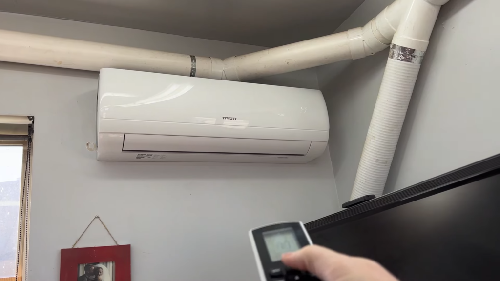
READY, SET… TEST!
Use the included remote to turn on the indoor unit and see if everything works! Most manufacturers recommend running the unit on both extremes for 15 minutes each. 15 very hot minutes, and 15 very cold minutes. If all is working as it should, congratulations! You did it! If anything isn’t working, walk carefully and slowly through the steps to see what might be missing. The first time I tried mine, I had forgotten to flip the AC Disconnect back to the “on” position. Easy fix.
Did you find this article helpful? If so, I’d love it if you left a comment sharing your success with me. These types of articles and videos take a long time to prepare so I really hope they help someone.
Good luck with your install!
All Products Used In This Install
These are affiliate links. They make me a small percentage of money and cost you the same.
- TOSOT Mini Split – All Options, Free Shipping! (Paid Link): https://geni.us/j4DaklC
- TOSOT 12k BTU Mini Split As Shown In These Images (Paid Link): https://geni.us/KvGoT1i
- UPDATE! I found a whole Vacuum Pump/Gauge/Adapter Kit for way less money! (Paid Link): https://geni.us/B49USF Please note that this is a 3 CFM pump, as opposed to the 5 CFM pump below.
- 5 CFM Vacuum Pump (Paid Link): https://geni.us/sIP8bYm
- Manifold Gauge Set (Paid Link): https://geni.us/O1HRDfZ
- Adapter from Gauge to Condenser (Paid Link): https://geni.us/M0ntsrl
- Wall Mount Bracket – Good (Paid Link): https://geni.us/99qpC1u
- Wall Mount Bracket – Better (Paid Link): https://geni.us/VTym
- Wall Mount Bracket – Best (Paid Link): https://geni.us/RGv9wMK
- 3/4” Auger Bit for Drilling Studs (Paid Link): https://geni.us/u4JWa6
- 2 1/8” Hole Saw (Paid Link): https://geni.us/0f7nL
- Klein Wire Stripper – Like I Use in the Video (Paid Link): https://geni.us/NUF0b
- Irwin Wire Cutter (Paid Link): https://geni.us/9XCrj0
- Nylog Blue – Not required but helpful (Paid Link): https://geni.us/qIqAA
- Drill Bit Extension for drilling through the wall (Paid Link): https://geni.us/Aumx
- AC Disconnect Box (Paid Home Depot Link): https://homedepot.sjv.io/3PMW1d
- 14/2 Romex, 25 ft – This costs a lot less on Amazon! (Paid Link): https://geni.us/DohdC7
- 14/2 Romex, 50 ft – This costs a lot less on Amazon: (Paid Link): https://geni.us/kqBMzAO
- 14/2 Romex, 100 ft – This costs a lot less on Amazon: (Paid Link): https://geni.us/t5wv
- 12/2 Romex, 25 ft – This costs a lot less on Amazon! (Paid Link): https://geni.us/u8faW
- 12/2 Romex, 50 ft – This costs a lot less on Amazon: (Paid Link): https://geni.us/RnFT2
- 12/2 Romex, 100 ft – This costs a lot less on Amazon: (Paid Link): https://geni.us/jjUS2Q
- Set of Adjustable Wrenches (Paid Link): https://geni.us/mzmvj
- Electrical Tape – 6 Pack (Paid Link): https://geni.us/ilmuQ3J
- Forstner Bit Set – I used a 1 3/8” on the outside of the shop (Paid Link): https://geni.us/323sZ
- Klein 11-in-1 Electrical Screwdriver – I LOVE this thing! (Paid Link): https://geni.us/NL41eT
- Basic Pipe Cutter with Reamer (Paid Link): https://geni.us/AngXexA
- 1/2” WHIP (Paid Link): https://geni.us/uuL3ec5
- IRWIN Vice Grips (Paid Link): https://geni.us/qwFf9
- 15 Amp Double Pole Breaker (Paid Link): https://geni.us/ue6D2E
- 20 Amp Double Pole Breaker (Paid Link): https://geni.us/rhSjH
- 25 Amp Double Pole Breaker (Paid Link): https://geni.us/OKlUix5
- 30 Amp Double Pole Breaker (Paid Link): https://geni.us/UiyTJn6
- Elbow (EMT Set Screw Conduit Body) (Paid Link): https://geni.us/PQsfM
- 3/4” EMT Insulated Compression Connectors (Paid Link): https://geni.us/IJ2PTFy
- 3/4” EMT Pipe Straps (Paid Link): https://geni.us/GDJh
- Big Stretch Caulk (Paid Link): https://geni.us/6SAfO
- Dripless Caulk Gun (Paid Link): https://geni.us/hRY6FgS
Your home’s HVAC system is one of the most important components in keeping your home comfortable all year round. Watch HERE to see what common mistakes to avoid –
Common Mistakes to Avoid with Your HVAC System
An energy efficient home can save you so much money. Every home needs occasional upgrades to make it more energy efficient. Click HERE for some simple and easy ideas to achieve this efficiency-
Top Methods for an Energy Efficient Home.
Refrigerant? You evacuated the line but never put in refrigerant?
The refrigerant comes in the condenser. When you open the lines, it releases the refrigerant into the lines.
Great guide, made me a bit more confident in going the DIY route. As for the TOSOT, it appears as though they have Wifi units, and an app ( https://play.google.com/store/apps/details?id=com.tosot.iot&hl=en_US&gl=US )
I’m looking at one single zone unit, and two 4-zone units. So there would be a lot more vacuum work, but if I’m saving $1500+ I think it’s worth it.
Nice! And yes, I agree that it’s worth the extra work when you’re saving that much. Best of luck on the project!